Low-Temperature Control, Heat Rejection, and Thermal Stability Across Marine Plants
System Group: Cooling & Heat Transfer
Primary Role: Controlled removal of heat below ambient temperature for preservation, process stability, comfort, and equipment protection
Applies To: Merchant Ships · Offshore Platforms & Rigs · Superyachts · Naval & Special Vessels
Interfaces: Seawater Cooling · HT/LT Freshwater · Heat Exchangers · HVAC · Electrical Systems · Automation
Operational Criticality: Continuous (often non-redundant for mission or habitability)
Failure Consequence: Food loss → habitability failure → electronics trips → process shutdown → safety risk
Refrigeration is not “cold making”.
It is forced heat relocation against the natural gradient, and it is therefore one of the most energy-intensive and failure-sensitive systems onboard.
Contents
- System Purpose and Design Intent
- Refrigeration Fundamentals (Marine Context)
- Boundaries, Interfaces, and Separation Philosophy
- Refrigeration and Chilled Water Architecture Across Marine Sectors
4.1 Merchant Ships
4.2 Offshore Platforms and Rigs
4.3 Superyachts and High-Comfort Vessels - Major Refrigeration and Chilled Water Systems
5.1 Direct Expansion (DX) Refrigeration
5.2 Central Refrigeration Plants
5.3 Chilled Water Systems
5.4 Cascade and Low-Temperature Systems - Major Machinery and Components
6.1 Compressors
6.2 Condensers
6.3 Evaporators
6.4 Expansion Devices
6.5 Refrigerants and Oils
6.6 Controls, Sensors, and Safeties - Control Under Real Operating Conditions
- Fouling, Leakage, and Degradation Reality
- Human Oversight, Watchkeeping, and Engineering Judgement
- Relationship to Adjacent Systems and Cascading Effects
1. System Purpose and Design Intent
Refrigeration and chilled water systems exist to maintain thermal conditions that cannot occur naturally onboard.
They protect:
- perishable stores
- pharmaceuticals and chemicals
- electronic equipment
- living spaces
- process streams offshore
Unlike cooling systems that merely reject heat, refrigeration systems must:
- extract heat from cold spaces
- compress and relocate it
- reject it at a higher temperature elsewhere
This makes them:
- power intensive
- control sensitive
- vulnerable to degradation
The design intent is continuous, predictable cold production, not peak performance.
2. Refrigeration Fundamentals (Marine Context)
Marine refrigeration is based on the vapour compression cycle:
- Heat is absorbed in the evaporator
- Refrigerant vapour is compressed
- Heat is rejected in the condenser
- Pressure is reduced through expansion
- The cycle repeats
This cycle operates under constraints unique to ships:
- variable seawater temperature
- vessel motion and vibration
- space and noise limitations
- intermittent load profiles
- limited redundancy
Refrigeration systems rarely fail suddenly.
They fail through loss of margin.


3. Boundaries, Interfaces, and Separation Philosophy
Refrigeration systems sit at critical interfaces:
- cold spaces ↔ machinery spaces
- electrical power ↔ thermal rejection
- freshwater ↔ seawater cooling
They must be isolated from:
- bilge contamination
- firemain systems
- uncontrolled drainage
Heat rejection usually occurs via:
- seawater-cooled condensers
- LT freshwater circuits feeding central coolers
Loss of separation leads to:
- refrigerant contamination
- condenser fouling
- rapid performance collapse

4. Refrigeration and Chilled Water Architecture Across Marine Sectors
4.1 Merchant Ships
On merchant vessels, refrigeration serves:
- provision rooms
- reefer containers
- air-conditioning via chilled water
Systems are:
- robust
- energy conscious
- designed for minimal intervention
Failure impacts cargo, crew welfare, and compliance.


4.2 Offshore Platforms and Rigs
On offshore installations, refrigeration becomes process-critical.
Used for:
- gas dehydration
- hydrocarbon dew point control
- chemical storage
- HVAC for enclosed modules
Systems are:
- redundant
- continuously monitored
- tightly interlocked
Loss of refrigeration may force process shutdown.

4.3 Superyachts and High-Comfort Vessels
On superyachts, chilled water systems dominate.
They serve:
- zoned accommodation HVAC
- galleys and cold rooms
- wine cellars and specialty storage
- noise-isolated comfort cooling
Design priorities include:
- silence
- vibration isolation
- redundancy without visible machinery
Comfort systems may appear separate — but they rely on the same thermal foundations as industrial plants.


5. Major Refrigeration and Chilled Water Systems
5.1 Direct Expansion (DX) Refrigeration
DX systems cool spaces directly via refrigerant evaporation in local evaporators.
Advantages:
- simplicity
- high efficiency
Limitations:
- leak sensitivity
- limited distribution distance
- maintenance complexity in occupied spaces
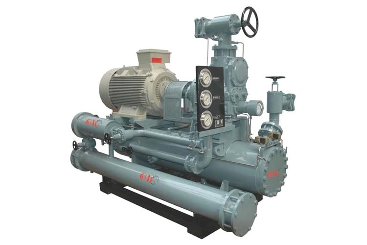
5.2 Central Refrigeration Plants
Central plants use multiple compressors feeding several evaporators.
Advantages:
- redundancy
- easier maintenance
- consolidated control
They concentrate risk and demand disciplined monitoring.
5.3 Chilled Water Systems
Chilled water systems decouple refrigeration from end users.
Refrigeration produces cold water, which is distributed to:
- air handling units
- fan coils
- process coolers
This architecture improves flexibility and comfort control at the cost of efficiency.
5.4 Cascade and Low-Temperature Systems
Used for:
- ultra-low temperature storage
- LNG-related processes
- specialty offshore applications
These systems use multiple refrigerants and stages, increasing complexity and failure sensitivity.
6. Major Machinery and Components
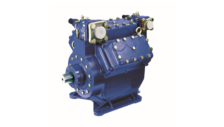
6.1 Compressors
Types include:
- reciprocating
- screw
- scroll
- centrifugal (large plants)
Compressors define:
- capacity
- efficiency
- vibration
- oil management complexity
They are the primary failure driver in refrigeration systems.
6.2 Condensers
Condensers reject heat to:
- seawater
- freshwater circuits
- air (limited use)
Fouling or scaling here raises discharge pressure and destroys efficiency long before alarms trigger.

6.3 Evaporators
Evaporators absorb heat from:
- air
- water
- process fluids
Ice formation, oil logging, and airflow restriction silently reduce capacity.
6.4 Expansion Devices
Expansion valves control refrigerant flow and evaporator pressure.
Poor control causes:
- hunting
- liquid carryover
- compressor damage
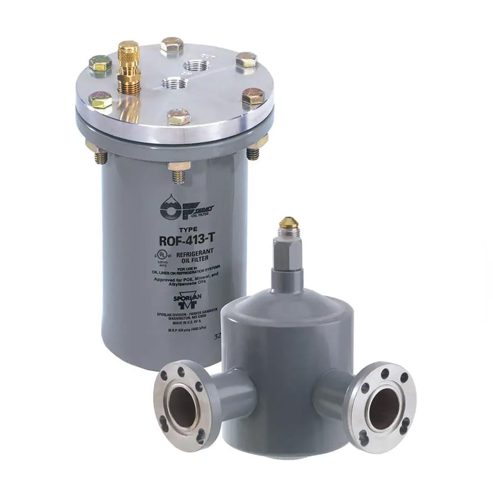
6.5 Refrigerants and Oils
Modern marine refrigerants are selected under:
- environmental regulation
- efficiency demands
- safety classification
Oil compatibility is critical. Oil migration is a common hidden failure mode.

6.6 Controls, Sensors, and Safeties
Refrigeration relies heavily on:
- pressure switches
- temperature sensors
- oil level controls
- safety cut-outs
Sensor drift leads to false confidence.
7. Control Under Real Operating Conditions
Marine refrigeration must cope with:
- varying ambient seawater temperature
- fluctuating electrical supply
- intermittent load
- fouled heat rejection surfaces
Systems compensate until margin disappears.
At that point, shutdowns become frequent and unexplained.
8. Fouling, Leakage, and Degradation Reality
Refrigeration systems degrade through:
- condenser fouling
- refrigerant leakage
- oil contamination
- control instability
Small leaks reduce capacity long before alarms detect them.
9. Human Oversight, Watchkeeping, and Engineering Judgement
Automation reports pressures and temperatures.
Engineers detect:
- rising compressor run time
- unstable suction pressure
- frequent defrost cycles
- unexplained power increase
Cold failure is usually preceded by behavioural changes, not alarms.
10. Relationship to Adjacent Systems and Cascading Effects
Refrigeration failure propagates into:
- HVAC collapse
- electrical overload
- food safety loss
- process shutdown offshore
Because refrigeration depends on every cooling system above it, it fails last — and recovers slowest.