Waste Heat Utilisation, Energy Cascading, and Efficiency Preservation in Marine Plants
System Group: Cooling & Heat Transfer
Primary Role: Capture and reuse of unavoidable waste heat to reduce fuel consumption, stabilise temperatures, and support auxiliary services
Applies To: Merchant Ships · Offshore Platforms & Rigs · Superyachts · Naval & Special Vessels
Interfaces: Exhaust Systems · HT/LT Cooling · Boilers & Steam Systems · Heat Exchangers · HVAC · Electrical Power
Operational Criticality: Continuous (efficiency- and stability-critical)
Failure Consequence: Lost efficiency → higher fuel burn → thermal imbalance → auxiliary overload → operational penalties
Thermal recovery does not create energy.
It reclaims energy that would otherwise destabilise the plant.
Contents
- System Purpose and Design Intent
- Why Waste Heat Dominates Marine Energy Balance
- Boundaries, Interfaces, and Energy Cascading Philosophy
- Thermal Recovery Architecture Across Marine Sectors
4.1 Merchant Ships
4.2 Offshore Platforms and Rigs
4.3 Superyachts and High-Comfort Vessels - Major Thermal Recovery Systems
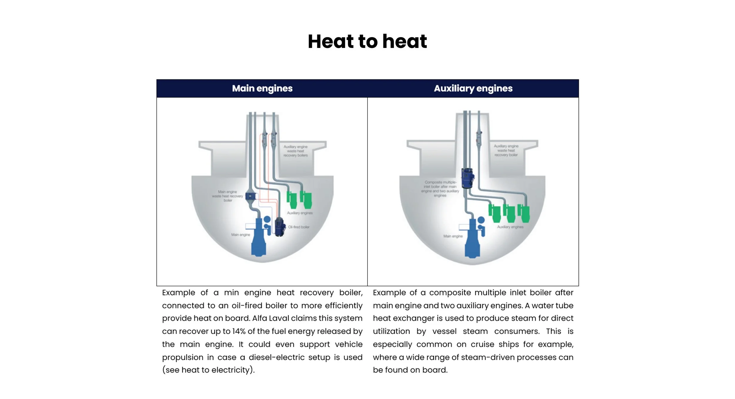
5.1 Exhaust Gas Economisers and WHR Boilers
5.2 Jacket Water and HT Circuit Heat Recovery
5.3 LT Circuit and Auxiliary Heat Reuse
5.4 Organic Rankine Cycle (ORC) and Power Recovery
5.5 Absorption Cooling and Heat-Driven Refrigeration - Major Machinery and Components
6.1 Economisers, Boilers, and Heat Recovery Units
6.2 Circulation Pumps, Valves, and Bypass Logic
6.3 Steam, Condensate, and Hot Water Distribution
6.4 Controls, Safeties, and Interlocks - Control Under Real Operating Conditions
- Fouling, Corrosion, and Degradation Reality
- Human Oversight, Watchkeeping, and Engineering Judgement
- Relationship to Adjacent Systems and Cascading Effects
1. System Purpose and Design Intent
Marine plants reject more energy as heat than they convert to useful work.
Thermal recovery exists to:
- reclaim a portion of that energy
- reduce fuel consumption
- stabilise thermal loads
- supply auxiliary services without additional firing
The intent is energy cascading, not maximum extraction.
Waste heat recovery systems must never compromise:
- engine operation
- exhaust backpressure limits
- cooling stability
- corrosion margins
An efficient plant is useless if it is unstable.
2. Why Waste Heat Dominates Marine Energy Balance
In a typical diesel engine:
- ~40–45% becomes shaft power
- ~25–30% exits via exhaust gas
- ~15–20% is removed by cooling systems
- the remainder is lost through radiation and friction
That rejected heat:
- must be removed anyway
- already destabilises the plant
- represents recoverable energy if managed correctly
Thermal recovery reduces cooling demand first, fuel demand second.


3. Boundaries, Interfaces, and Energy Cascading Philosophy
Thermal recovery systems sit at dangerous interfaces:
- hot exhaust gas ↔ water/steam
- engine cooling ↔ auxiliary consumers
- high temperature ↔ corrosion-prone surfaces
Energy must be cascaded:
- from high temperature to lower temperature users
- without mixing fluids
- without exceeding material limits
Attempting to recover “too much” heat results in:
- exhaust fouling
- acid corrosion
- unstable engine operation
Recovery must always respect primary engine needs
4. Thermal Recovery Architecture Across Marine Sectors
4.1 Merchant Ships
On merchant vessels, thermal recovery is used for:
- steam generation
- fuel heating
- domestic hot water
- tank heating
- occasionally electrical generation
Systems prioritise:
- robustness
- predictable output
- minimal intervention
Fuel savings are meaningful only when stability is preserved.
4.2 Offshore Platforms and Rigs
Offshore installations use thermal recovery to:
- support continuous processes
- reduce gas turbine firing
- supply heating for separation, dehydration, and utilities
Systems are:
- heavily interlocked
- redundancy-focused
- closely monitored
Loss of recovery may force increased fuel use or process derating.

4.3 Superyachts and High-Comfort Vessels
On superyachts, recovered heat is used for:
- domestic hot water
- pool heating
- spa and wellness systems
- HVAC reheat
Design constraints include:
- noise
- vibration
- aesthetic integration
Recovery systems must be invisible in operation.

5. Major Thermal Recovery Systems
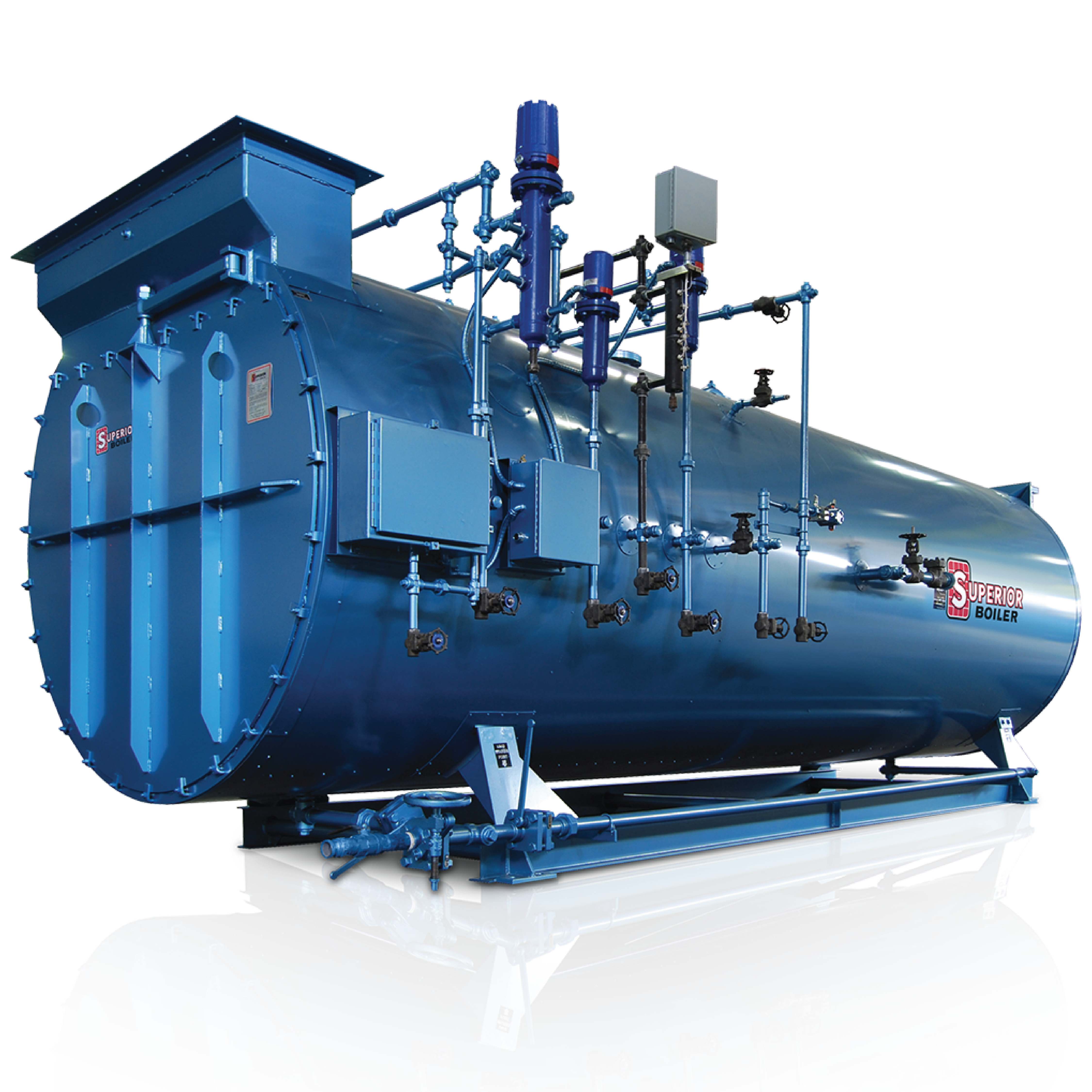
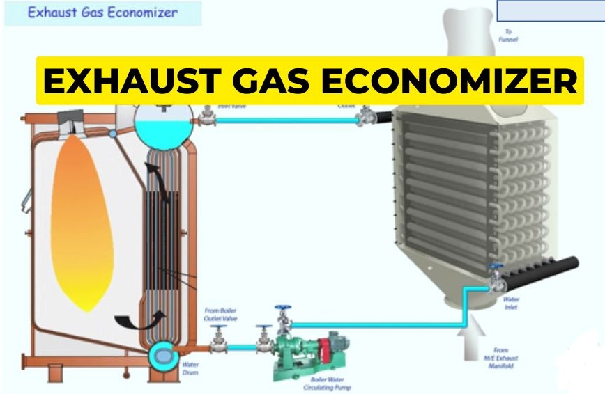
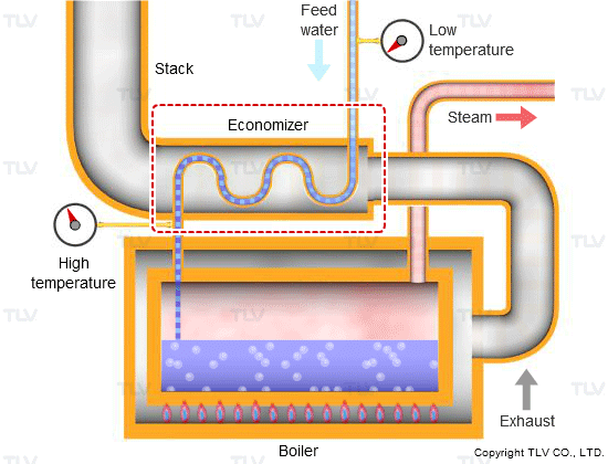
5.1 Exhaust Gas Economisers and WHR Boilers
Exhaust gas economisers capture heat from engine exhaust to produce:
- steam
- hot water
They are exposed to:
- soot fouling
- sulphuric acid condensation
- thermal cycling
Backpressure control is critical. Excessive restriction damages engine performance.
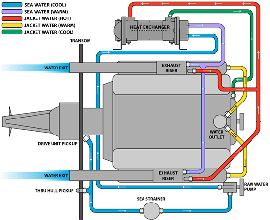
5.2 Jacket Water and HT Circuit Heat Recovery
HT cooling water contains substantial recoverable heat.
It can supply:
- domestic hot water
- fuel heating
- space heating
- absorption chillers
This recovery must never destabilise HT temperature control.
5.3 LT Circuit and Auxiliary Heat Reuse
Lower-grade heat from LT systems can be reused for:
- accommodation heating
- ventilation reheating
- tank warming
LT recovery is sensitive to load variation and fouling.
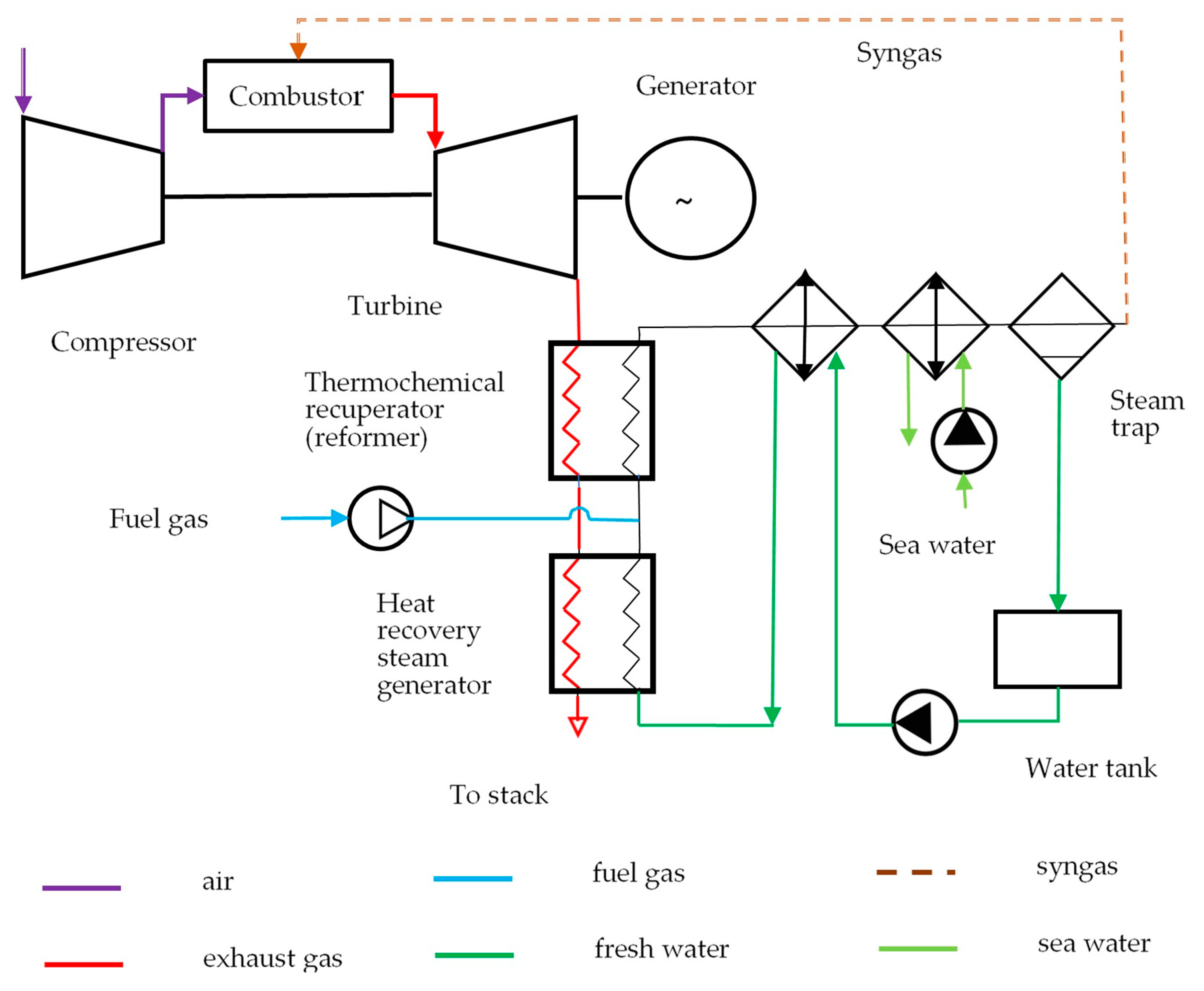
5.4 Organic Rankine Cycle (ORC) and Power Recovery
ORC systems convert low-grade heat into electrical power.
They add:
- complexity
- control challenges
- maintenance burden
Their viability depends on stable heat availability.
5.5 Absorption Cooling and Heat-Driven Refrigeration
Recovered heat can drive absorption chillers to produce cooling.
This trades:
- electrical load reduction
- for thermal system complexity
Used primarily on offshore platforms and large vessels.

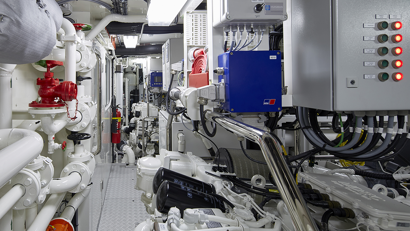
6. Major Machinery and Components
6.1 Economisers, Boilers, and Heat Recovery Units
These units define recovery capacity and fouling risk.
Tube condition directly determines efficiency and safety.
6.2 Circulation Pumps, Valves, and Bypass Logic
Bypass arrangements protect systems during:
- low load
- start-up
- fouling conditions
Bypass misuse is a common source of instability.
6.3 Steam, Condensate, and Hot Water Distribution
Recovered energy is useless without reliable distribution.
Leaks, traps, and condensate return failures silently erode benefits.
6.4 Controls, Safeties, and Interlocks
Thermal recovery systems rely on:
- temperature limits
- pressure relief
- backpressure monitoring
- automated bypass
Control failures often cascade into unrelated systems.
7. Control Under Real Operating Conditions
Thermal recovery is load-dependent.
At low engine load:
- exhaust temperature drops
- acid risk increases
- recovery potential collapses
Systems must adapt without manual intervention.
8. Fouling, Corrosion, and Degradation Reality
Recovery systems are exposed to:
- acidic condensates
- soot deposition
- cyclic thermal stress
Fouling reduces recovery first, then creates corrosion.
Cleaning frequency is a leading indicator of health.
9. Human Oversight, Watchkeeping, and Engineering Judgement
Automation manages valves. Engineers manage risk.
Experienced watchkeepers notice:
- rising exhaust backpressure
- increasing soot load
- unstable HT temperatures
- declining recovery output
Efficiency losses usually precede alarms.