Directional Authority, Hydraulic Reality, and the Consequences of Control Loss
ENGINE ROOM → Propulsion & Transmission
System Group: Steering & Directional Control
Primary Role: Conversion of helm command into controlled vessel heading change
Interfaces: Bridge Control · Hydraulics · Power Supply · Hull Structure · Propulsion Flow
Operational Criticality: Safety-Critical
Failure Consequence: Loss of heading control → collision / grounding risk → SOLAS non-compliance
Steering gear is not an auxiliary system.
It is the final authority layer between propulsion and navigational safety.
Position in the Plant
The steering system exists to convert small control inputs at the bridge into large hydrodynamic forces acting on the hull. It operates continuously under load, often unnoticed, until it fails — at which point failure is immediately operational.
From an engineering perspective, steering gear occupies a unique position. It is simultaneously:
- a hydraulic power system
- a mechanical force transmission system
- a control and redundancy system
- a statutory safety installation
Unlike propulsion machinery, steering gear is legally required to fail safely, redundantly, and predictably. This requirement shapes every aspect of its design.
Contents
System Purpose and Design Intent
Hydrodynamic Role of the Rudder
Ram vs Rotary Vane Steering Gear
Hydraulic Power and Redundancy Philosophy
Control, Feedback, and Follow-Up Systems
Structural Loading and Fatigue Reality
Failure Development and Damage Progression
Human Oversight and Emergency Operation
1. System Purpose and Design Intent
The purpose of the steering system is directional authority under all operating conditions.
Design intent prioritises:
- redundancy over efficiency
- predictability over responsiveness
- survivability over optimisation
Steering systems must operate during:
- normal navigation
- manoeuvring
- heavy weather
- partial machinery failure
They are designed to remain functional even when other systems are compromised.
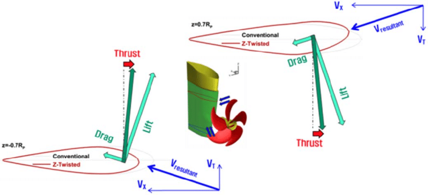
2. Hydrodynamic Role of the Rudder
The rudder generates lift through flow deflection. Its effectiveness depends on:
- propeller wash velocity
- rudder profile and area
- angle of attack
At low speed, rudder authority is marginal. At high speed, forces increase exponentially.
Hydrodynamic loading increases rapidly with rudder angle. Small increases beyond design angles result in:
- stall
- vibration
- excessive stock torque
The rudder does not fail gently. Structural overload occurs suddenly when limits are exceeded.
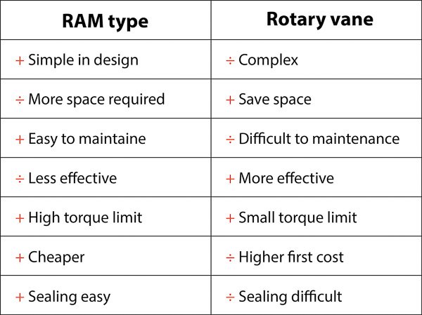
3. Ram vs Rotary Vane Steering Gear
Ram-Type Steering Gear
Ram systems use hydraulic cylinders acting on tiller arms.
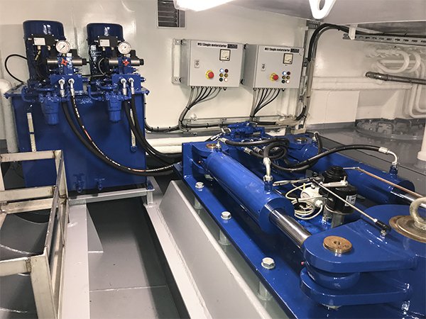
They offer:
- mechanical transparency
- clear load paths
- simpler fault diagnosis
Failure modes include:
- seal leakage
- internal bypassing
- cylinder rod damage
Rotary Vane Steering Gear
Rotary vane systems generate torque within a compact housing.
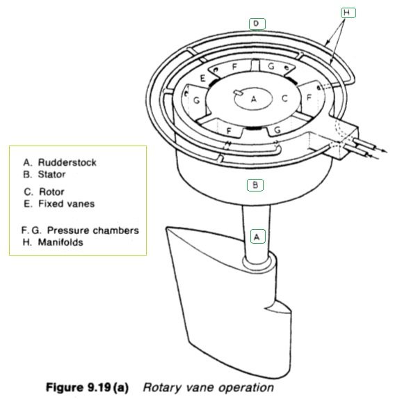
They offer:
- reduced footprint
- high torque density
But they introduce:
- internal sealing complexity
- limited visual inspection
- sensitivity to contamination
Leakage in vane systems often progresses internally before becoming externally visible.
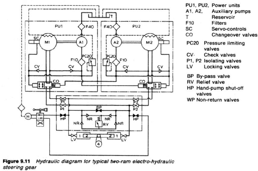
4. Hydraulic Power and Redundancy Philosophy
Steering gear hydraulics are designed around duplication, not efficiency.
SOLAS requires:
- independent power units
- separate control circuits
- automatic changeover
Hydraulic failure is assumed, not treated as exceptional.
Oil cleanliness is critical. Contamination accelerates seal wear, valve sticking, and loss of response accuracy.
A steering system that still “moves” but responds slowly is already degraded.
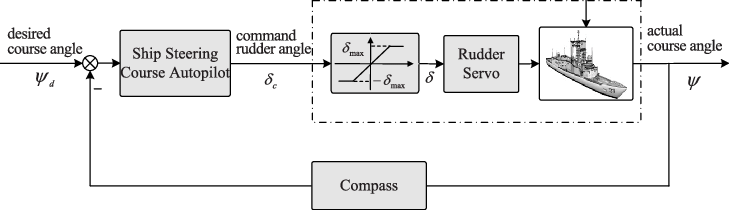
5. Control, Feedback, and Follow-Up Systems
Steering control depends on accurate position feedback.
Follow-up systems ensure commanded rudder angle matches actual rudder position. Drift or loss of feedback results in:
- hunting
- overshoot
- delayed response
Bridge indications may appear stable while mechanical lag accumulates.
Manual and local control modes are not backup conveniences. They are survival systems.
6. Structural Loading and Fatigue Reality
Rudder stocks and pintles experience:
- cyclic bending
- torsional load
- shock loading in heavy seas
Fatigue accumulates invisibly.
Bearing wear increases clearance, allowing impact loading during rudder reversals. This accelerates crack initiation at stress concentrations.
Structural steering failures are rare but catastrophic.
7. Failure Development and Damage Progression
Steering failures typically progress through:
- hydraulic leakage or contamination
- response degradation
- feedback error
- asymmetric movement
- loss of control authority
Complete failure is often preceded by subtle behavioural changes.
8. Human Oversight and Emergency Operation
Engineers protect steering systems by:
- monitoring response time, not just angle
- maintaining oil cleanliness
- testing emergency modes regularly
A steering system that has not been exercised under emergency control is unproven.
Judgement prevents loss of control long before alarms activate.