Working the Ship, Controlling Stored Energy, and Why Most Failures Are Load-Induced
ENGINE ROOM → Auxiliary & Support Systems
System Group: Deck Operations & Supporting Machinery
Primary Role: Handling the vessel, cargo, and external interfaces safely and repeatedly
Interfaces: Power Generation · Hydraulics · Steering Gear · Structural Systems · Safety Systems
Operational Criticality: Intermittent but High Consequence
Failure Consequence: Loss of control → cargo damage → personnel injury → operational stoppage
Deck and auxiliary machinery do not propel the ship.
They are what make the ship usable.
Position in the Plant
Deck and auxiliary machinery occupy a boundary role between structure, machinery, and operations. They convert stored energy — electrical, hydraulic, or pneumatic — into controlled mechanical work that allows the vessel to anchor, moor, manoeuvre, load, discharge, and respond to emergencies.
From an engineering perspective, these systems are characterised by intermittent high load, exposure to weather, salt, impact, and misuse. They are rarely loaded gently and almost never operated under ideal conditions.
Most deck machinery failures are not design failures.
They are load management failures.
Contents
System Purpose and Design Intent
Deck Machinery and On-Deck Operations
Auxiliary Machinery and Supporting Systems
Power Sources and Drive Philosophy
Structural Interaction and Load Paths
Wear, Exposure, and Environmental Degradation
Failure Development and Damage Progression
Human Oversight and Engineering Judgement
1. System Purpose and Design Intent
The design intent of deck and auxiliary machinery is reliable force application under variable and often hostile conditions.
Deck machinery exists to transmit force externally: into anchor chains, mooring lines, cargo gear, hoses, and lifting appliances. Auxiliary machinery exists to support the vessel internally: generating power, moving fluids, supplying air, and enabling safety systems.
Together, they allow the ship to function as a working platform rather than a moving hull.
Design assumptions include correct load application, trained operation, and intact structural foundations. When these assumptions are violated, damage accumulates rapidly.
2. Deck Machinery and On-Deck Operations
Deck machinery refers to all equipment installed on deck that performs external work on the vessel.
Deck Machinery Equipment Groups and Operational Reality
Deck machinery is not a collection of isolated machines. It is a coordinated system of force application, load restraint, and controlled motion, distributed across the deck and tied directly into the ship’s structure. Each group of equipment is designed around a specific operational problem, but all share common characteristics: intermittent high load, exposure to the marine environment, and severe consequences when misused.
Understanding deck machinery requires understanding what force is being applied, where it is reacted, and how it is controlled.
Anchoring Equipment
Anchoring equipment exists to transfer large, dynamic loads from the seabed into the hull structure in a controlled manner. It is among the most heavily loaded machinery on board and is routinely subjected to shock loads well above steady-state design values.
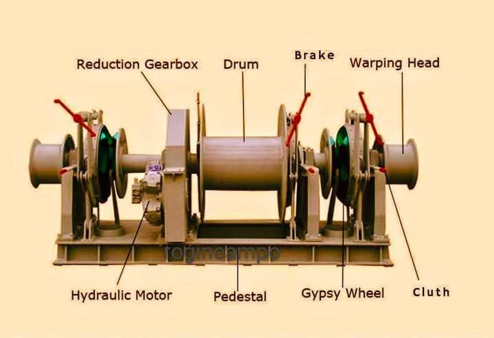
The windlass is the primary anchor handling machine on most vessels, combining chain handling, hoisting, and controlled paying out. During anchoring, the windlass transitions rapidly from a drive machine to a controlled braking system. Its most critical components are therefore not the motors, but the brakes, clutches, and foundations that absorb energy when the anchor takes load.
On vessels without a combined windlass, dedicated anchor winches perform a similar function but often with less integration between chain handling and braking. These systems rely heavily on correct interaction with chain stoppers and devil’s claws, which are not drive machinery but load-securing devices. Their role is structural, not mechanical, and misuse leads directly to deck damage or chain failure.
Capstans provide vertical line handling for lighter loads or auxiliary operations. They are simple machines, but frequently abused by attempting to exceed their intended duty, leading to motor overheating or foundation distortion.
Anchor chain tensioners and handling rollers do not generate force but guide it. Poor alignment or wear in these components concentrates stress, accelerating chain wear and increasing the likelihood of jumping, snatching, or shock loading.
Fairleads and rollers are often treated as passive hardware, yet they define load direction. Misalignment here creates forces that no brake or clutch can compensate for.
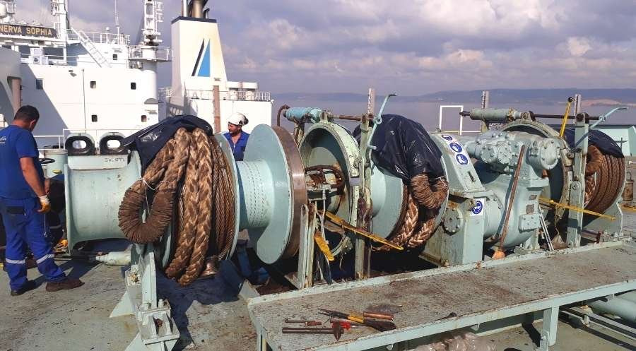
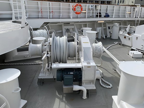
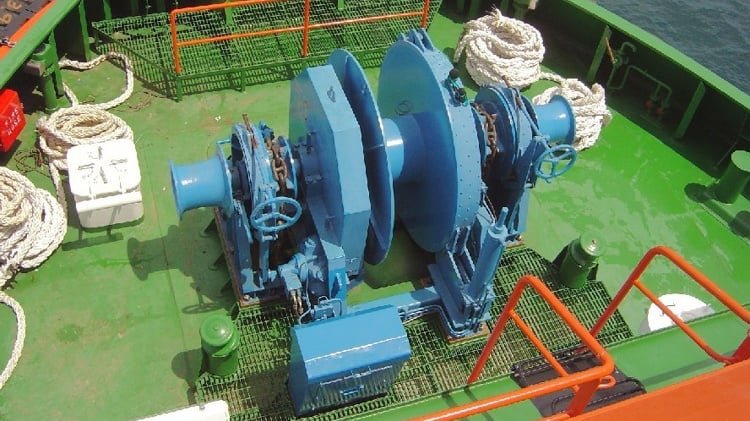
Mooring Machinery
Mooring machinery controls the ship’s interface with fixed infrastructure under constantly changing environmental conditions. Mooring winches are designed to apply, hold, and adjust line tension as wind, tide, and loading change.
Single-drum winches offer simplicity but limited flexibility. Double-drum and split-drum winches allow multiple lines or configurations, but introduce complexity in brake management and load sharing. Errors here often result in uneven loading and unexpected line failure.
Self-tensioning and automatic mooring winches introduce control systems that continuously adjust line tension. While these systems reduce crew workload, they can mask deteriorating conditions until limits are reached suddenly. Automation does not eliminate physics; it delays its visibility.
Capstans supplement winches for handling lighter lines or positioning tasks, but their frequent misuse as load-holding devices leads to premature failure.
Brake systems and clutches are the true safety-critical components of mooring machinery. A winch motor can stall harmlessly; a failed brake releases stored energy violently. Brake condition, adjustment, and cooling determine survivability under peak load.
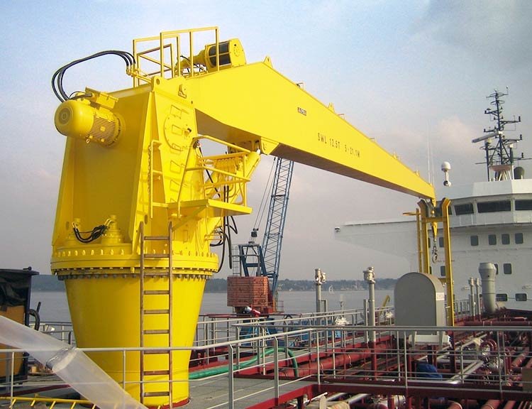
Cargo Handling Machinery
Cargo handling machinery converts deck space into productive capability. Cranes, winches, and derricks lift, position, and transfer loads whose mass and geometry vary continuously.
Deck cranes — whether electro-hydraulic, electric luffing, or knuckle-boom — rely on precise control of load moment rather than absolute load weight. Overloading often occurs not because rated capacity is exceeded, but because radius, slew speed, or dynamic effects are ignored.
Cargo winches and derrick systems are mechanically simpler but equally unforgiving. Shock loading during lifting or lowering damages wire ropes, drums, and foundations long before visible failure occurs.
Hose-handling cranes on tankers and offshore vessels deal with awkward, flexible loads that introduce unpredictable dynamic forces. Control finesse matters more than raw power.
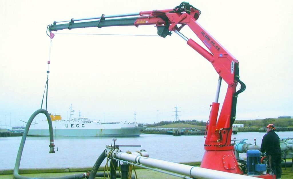
Cargo oil pumps, though often located below deck, are operationally inseparable from deck machinery. Their performance dictates cargo handling rates and safety margins, and their failure halts deck operations entirely.
Specialised equipment such as grab winches, fishing winches, trawl winches, and towing winches are designed for continuous heavy-duty operation. They are structurally robust but sensitive to misuse, particularly during snatch loading or when control systems lag operator input.
Steering and Manoeuvring-Related Deck Equipment
Steering gear machinery represents the most safety-critical deck-linked system on board. Hydraulic rams or rotary vane units translate control input into rudder movement against hydrodynamic load.
Emergency steering arrangements exist because steering gear failure is not hypothetical. Rudder carriers and tiller arms transmit enormous forces into the hull, and any loss of integrity here results in immediate loss of control.
Local thruster control machinery, where deck-mounted, shares the same vulnerability: high torque, rapid response demand, and intolerance of contamination or delayed maintenance.
Launching and Recovery Equipment
Launching and recovery equipment is designed for infrequent use under the worst possible conditions.
Lifeboat davits — whether gravity, free-fall, or rescue boat systems — must function reliably after long periods of inactivity. Winches and release mechanisms are prone to corrosion, seizure, and misadjustment precisely because they are not exercised regularly.
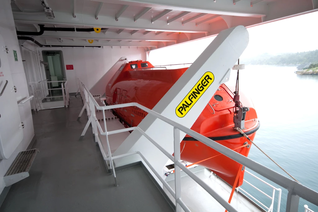
Embarkation ladders and platforms form part of the system even though they are not powered. Their failure compromises evacuation regardless of machinery condition.
Offshore and Specialised Deck Machinery
Offshore vessels introduce machinery designed to control loads that move independently of the ship.
Anchor handling winches on AHTS vessels manage massive dynamic loads transmitted through wire and chain. Tug winches operate under rapidly changing tension as tow geometry evolves.
Heave-compensated winches and ROV handling systems attempt to decouple ship motion from load motion. When they fail, the resulting shock loads are often destructive.
Cable laying equipment and wire rope tensioners operate under precise control requirements, where small errors result in costly damage rather than immediate safety incidents.
Mooring tension monitoring systems provide information, not protection. They rely on engineers to interpret trends and act before limits are reached.
Supporting Deck Machinery Systems
No deck machinery operates alone. Hydraulic power units supply energy, and their condition dictates the behaviour of every connected machine. Local control stations and panels introduce electrical and electronic vulnerability into otherwise mechanical systems.
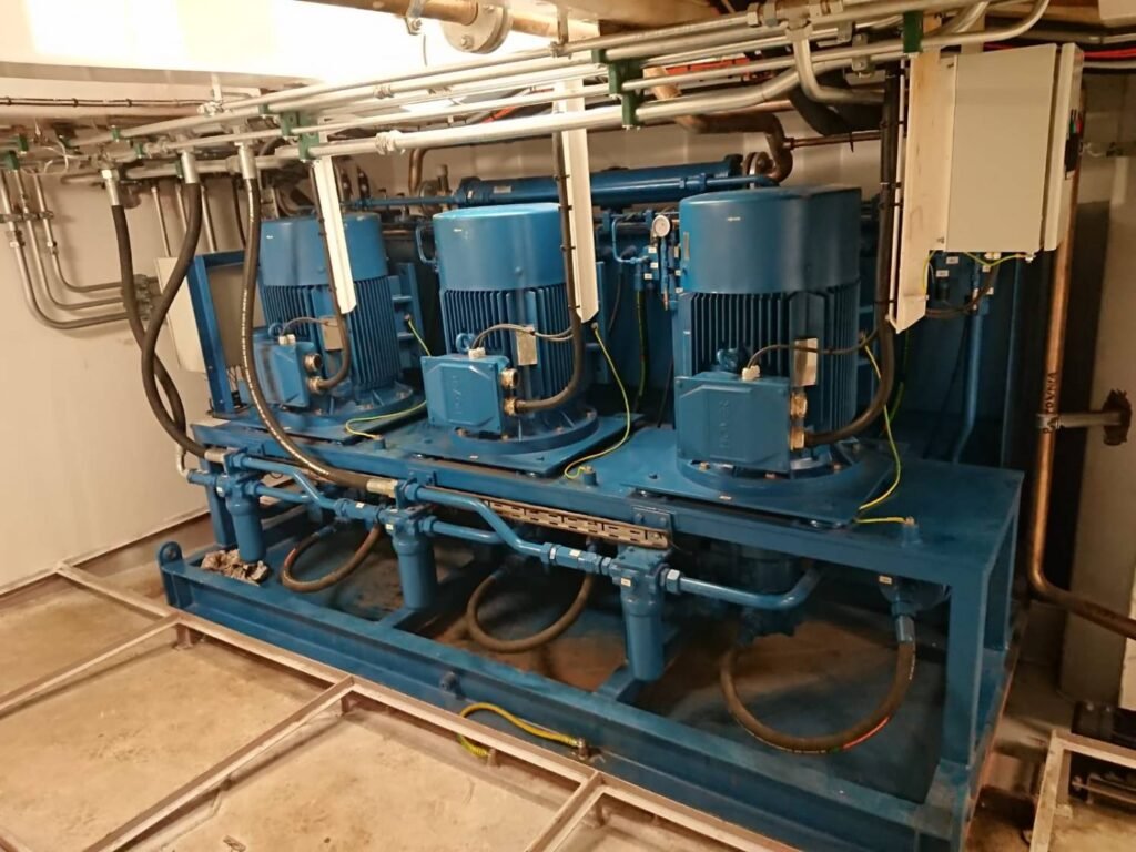
Brake cooling systems, lubrication circuits, and load monitoring devices exist to preserve margins. When neglected, margins disappear quietly.
Load limiters and monitoring systems are advisory tools, not substitutes for judgement.
Common Drive Types and Their Implications
Electric motor-driven machinery offers simplicity and clean operation but introduces transient electrical loads. Electro-hydraulic systems deliver power density and control but add contamination and fire risk. Fully hydraulic systems tolerate shock but require rigorous cleanliness control. Pneumatic drives persist in legacy or specialised roles, limited by efficiency and control precision.
Drive choice defines failure mode, not failure likelihood..
3. Auxiliary Machinery and Supporting Systems
Auxiliary machinery encompasses all non-propulsion systems required to support vessel operation.
Power generation systems supply electrical energy to deck equipment, often under high transient load. Air compressors provide starting air, control air, and service air, with deck operations frequently imposing rapid demand changes. Pumps move fuel, cooling water, bilge water, ballast, and cargo fluids, linking deck activity directly to internal machinery spaces.
HVAC and refrigeration systems support habitability and cargo preservation, while freshwater production and sewage treatment sustain crew and regulatory compliance.
Firefighting systems, emergency generators, and lifeboat engines are auxiliary machinery in the strictest sense: rarely used, legally mandated, and expected to work instantly under worst conditions.
Firefighting Systems
Shipboard firefighting systems are not single installations. They are layered defensive architectures designed to detect, contain, and suppress fires in environments where escape, external assistance, and structural separation are severely limited.
Unlike shore-based facilities, a ship cannot evacuate a burning compartment and wait for help. Fire must be detected early, contained immediately, and either extinguished or controlled with the resources already on board. For this reason, marine firefighting systems combine early detection, segmentation, and multiple suppression strategies, each tailored to the type of space, fuel load, and escalation risk involved.
The design philosophy assumes that no single system will be sufficient under all conditions. Firefighting at sea is therefore based on redundancy, overlap, and the ability to continue operating under degraded conditions, including loss of main power.
Detection and Early Warning
Detection is the first and most critical layer of shipboard fire defence. Smoke and heat detection systems provide early warning before fire growth reaches a point where suppression becomes complex or dangerous.
Smoke detectors dominate accommodation and control spaces where smouldering fires are likely, while heat detectors are favoured in machinery spaces where background aerosols and temperature fluctuations would cause nuisance alarms. Fire alarm panels integrate these signals and initiate local and remote alerts, buying time for response and isolation.
Detection does not extinguish fires, but it defines the response window. Delayed detection is the most common precursor to catastrophic engine room fires.
Fire Pumps, Power Independence, and Water Supply
Water remains the primary firefighting medium on most ships. Fire pumps supply this water through the fire main to hydrants, hoses, and fixed systems.
Main fire pumps are typically electrically driven and located within machinery spaces. Emergency fire pumps are physically separated, often diesel-driven, and positioned outside the main engine room to ensure availability during blackout or machinery space fire. This separation is not redundancy for convenience; it is survivability by design.
Fire mains form a ring or zoned distribution system with isolation valves that allow damaged sections to be cut out while maintaining pressure elsewhere. Hydrants, hoses, and nozzles provide manual firefighting capability, with jet and spray patterns chosen based on cooling or boundary control requirements.
A fire main that cannot be sectionalised is a single-point failure.
Containment: Doors, Dampers, and Oxygen Control
Fire suppression is ineffective without containment.
Fire doors, bulkheads, and deck penetrations define fire zones. Dampers in ventilation systems prevent the uncontrolled spread of smoke and oxygen, while fire flaps isolate machinery and accommodation spaces automatically or manually.
Containment systems are passive most of the time, which makes their maintenance critical. A fire door wedged open or a damper seized in position defeats every active suppression system downstream.
Firefighting systems are designed to remove heat. Containment systems are designed to remove oxygen and prevent spread. Both are required.
Fixed Fire Suppression Systems
Fixed firefighting systems are installed where manual intervention is unsafe, impractical, or too slow.
Water mist systems, such as high-pressure fine mist installations, have become increasingly common in machinery spaces and accommodation areas. By producing extremely small droplets, these systems absorb heat rapidly, displace oxygen locally, and reduce radiant energy without the massive water damage associated with traditional sprinklers. Their effectiveness depends on nozzle condition, pressure stability, and correct zoning.

Foam systems are used where hydrocarbon fires are the dominant risk. On tankers and chemical carriers, deck foam systems blanket cargo areas to suppress vapour release and prevent re-ignition. High-expansion foam is also used in enclosed spaces to smother fires by filling volume rapidly, but its deployment requires careful coordination to avoid structural or access hazards.
Carbon dioxide systems remain widely installed for total flooding of enclosed spaces such as engine rooms and cargo holds. CO₂ suppresses fire by displacing oxygen, but it is immediately lethal to personnel. Its use requires complete evacuation, space integrity, and disciplined procedural control. False activation or partial discharge renders the system unavailable when genuinely needed.
Inert gas systems, particularly on tankers, serve both firefighting and prevention roles. By reducing oxygen concentration below combustion thresholds, they suppress ignition risk in cargo spaces and tanks. Their effectiveness depends on continuous monitoring and gas purity.
Sprinkler systems dominate accommodation and public spaces, providing automatic suppression with minimal crew intervention. Their reliability hinges on valve integrity, corrosion control, and water supply availability.
Dry powder systems, whether fixed or portable, are reserved for specific hazards such as flammable gas fires. They are effective but create visibility and contamination problems, limiting their use.
System Selection by Space and Risk
Firefighting systems are matched to risk profile rather than convenience.
Machinery spaces rely on fixed suppression systems, boundary cooling, and ventilation control because manual firefighting is often impossible once a fire develops. Accommodation spaces prioritise early detection, sprinklers, and compartmentation to allow evacuation and control. Cargo holds and tanker decks use inert gas, foam, or water mist depending on cargo type and regulatory requirement. Helicopter decks and exposed areas rely on foam systems designed for rapid knockdown of fuel fires.
One system rarely protects every space effectively.
Isolation, Redundancy, and Regulatory Control
Isolation capability ensures that damage in one area does not disable the entire firefighting system. Redundancy ensures that no single failure — mechanical, electrical, or human — removes the ship’s ability to respond.
Emergency power supplies, independent pumps, duplicated control lines, and manual overrides exist because firefighting often coincides with blackout conditions.
All shipboard firefighting systems are governed by international regulations, primarily under the IMO framework and enforced through classification societies such as DNV, Lloyd’s Register, and ABS. These standards specify minimum capability, not operational excellence. Compliance does not guarantee readiness.
Engineering Reality
Firefighting systems are rarely used, which makes complacency their greatest enemy.
A system that passes inspection but has never been tested under realistic conditions is unproven. Valves seize, pumps degrade, sensors drift, and procedures are forgotten.
On a ship, fire escalation is measured in minutes. Engineering discipline determines whether those minutes are used effectively.
4. Power Sources and Drive Philosophy
Deck and auxiliary machinery are driven primarily by electric motors and hydraulic systems, with a declining presence of steam and pneumatic drives.
Electric drives offer simplicity, efficiency, and ease of control, but they impose transient loads on the electrical plant. Hydraulic drives deliver high power density and shock tolerance, but introduce leakage, contamination, and fire risk.
The choice of drive is a compromise between control, robustness, and maintainability. Hybrid arrangements are common, but they multiply interfaces and failure modes.
A drive system that appears oversized on paper may still fail in service if control logic and load sequencing are poorly understood.
5. Structural Interaction and Load Paths
Deck machinery does not act in isolation. Every force applied by a winch, crane, or windlass is transmitted into deck plating, foundations, and hull structure.
Poor alignment, corroded foundations, or unauthorised modifications concentrate stress and initiate cracking. These failures often appear structural but originate in machinery loading errors.
Foundation integrity is as critical as mechanical condition.
6. Wear, Exposure, and Environmental Degradation
Deck machinery lives in the harshest environment on the ship.
Salt spray, ultraviolet exposure, temperature cycling, and mechanical impact accelerate degradation. Lubrication is washed away. Coatings fail. Corrosion initiates at interfaces and fasteners.
Auxiliary machinery, though more protected, suffers from vibration, heat, and contamination driven by deck operations.
A deck winch that looks serviceable externally may be internally compromised.
7. Failure Development and Damage Progression
Failures typically progress through:
- overloading or shock loading
- accelerated wear and misalignment
- control or brake degradation
- structural or mechanical failure
- operational stoppage or accident
Damage often accumulates unnoticed until failure is sudden and hazardous.
8. Human Oversight and Engineering Judgement
Engineers protect deck and auxiliary machinery by:
- understanding load paths, not just motor ratings
- enforcing operational limits
- treating abnormal noise, vibration, or behaviour as early warnings
Deck machinery does not forgive misuse.
Auxiliary machinery does not compensate for it.
Judgement, not brute force, keeps these systems alive.
Relationship to Adjacent Systems and Cascading Effects
Failure propagates into:
- loss of anchoring or mooring capability
- cargo handling delays or incidents
- electrical instability
- safety system impairment
Deck and auxiliary machinery define the ship’s ability to interact safely with the world outside its hull.