Why This System Matters More Than Most Engineers Admit
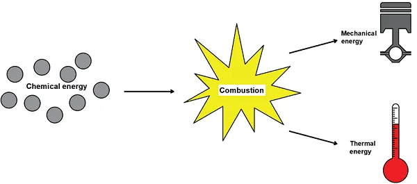
A modern marine diesel engine is thermodynamically brutal:
- < 50% of fuel energy becomes shaft power
- 25–35% leaves the engine through the exhaust
- The rest is scattered through charge air, jacket water, lube oil, radiation
The exhaust system is therefore not just gas piping.
It is:
- an energy recovery system
- an emissions control interface
- a turbocharger life limiter
- a major failure and fire risk
- a regulatory compliance boundary
Poor exhaust system design quietly increases fuel consumption, destroys turbochargers, cracks boilers, and violates IMO rules — often without obvious alarms.
This article treats the exhaust system as a complete thermodynamic and mechanical system, not a collection of pipes.
Table of Contents
- Energy Balance of Marine Engines
- Exhaust Gas Characteristics & Constraints
- Exhaust System Architecture (End-to-End)
- Turbochargers — First-Stage Energy Recovery
- Exhaust Gas Boilers (Economisers)
- Backpressure: The Silent Power Thief
- Waste Heat Recovery Technologies (WHR)
- Organic Rankine Cycle (ORC) Systems
- Power Turbines & Combined Systems
- Auxiliary Heat Uses (HVAC, Fuel, Water)
- Materials, Corrosion & Acid Dew Point
- Failure Modes & Real-World Damage
- Regulatory & IMO Drivers
- Engineering Takeaways
1. Energy Balance of Marine Engines
A typical large two-stroke engine (e.g. 70–90 MW):
| Energy Path | % of Fuel Energy |
|---|---|
| Shaft Power | ~48–50% |
| Exhaust Gas | 25–30% |
| Scavenge / Charge Air | 15–18% |
| Jacket Water | 5–7% |
| Lube Oil | 2–3% |
| Radiation | <1% |
The exhaust stream is:
- high temperature (300–500 °C)
- high mass flow
- continuous
This makes it the highest-value waste heat source onboard.
2. Exhaust Gas Characteristics & Constraints
Typical values downstream of turbocharger:
- Temperature: 280–420 °C
- Velocity: 35–50 m/s
- Pressure margin allowed: <350 mmWC
- Composition:
- CO₂
- H₂O vapour
- O₂ (residual)
- SOx / NOx
- soot & particulates
The exhaust system must balance:
- energy recovery
- pressure loss
- corrosion prevention
- noise control
You cannot optimise one without affecting the others.
3. Exhaust System Architecture (End-to-End)
Flow Path
- Cylinder exhaust valves
- Exhaust receiver (pulse smoothing)
- Turbocharger turbine
- Exhaust gas boiler / economiser
- Silencer / spark arrester
- Uptake & funnel
- Atmosphere
Every component adds pressure loss — and therefore fuel penalty.
4. Turbochargers — First-Stage Energy Recovery
Turbochargers already recover:
- 15–20% of exhaust energy
- convert it into scavenge air pressure
Key implications:
- Any downstream restriction reduces turbine efficiency
- Turbocharger matching assumes specific backpressure
- Excess pressure causes:
- reduced air mass flow
- higher exhaust temperature
- increased fuel consumption
This is why waste heat recovery cannot be bolted on blindly.
5. Exhaust Gas Boilers (Economisers)
Purpose
- Recover exhaust heat to generate:
- steam
- hot water
- thermal oil
Typical Uses
- Heating fuel & lube oil
- Tank heating
- Accommodation heating
- Desalination
- Steam turbines (where fitted)
Design Types
- Bare tube
- Finned tube (most common)
- Vertical / horizontal gas flow
Key Limits
- Pressure drop across EGB:
- ≤150 mmWC at MCR
- Outlet temperature:
- Must stay above acid dew point
6. Backpressure — The Silent Power Thief
Backpressure increases fuel consumption linearly.
Industry Rules of Thumb
- Exhaust velocity: 35–50 m/s
- Total backpressure after turbo:
- Design: 300 mmWC
- Absolute max: 350 mmWC
Consequences of Excess Backpressure
- Turbocharger overspeed or surge
- High exhaust valve temperatures
- Cracked exhaust manifolds
- Increased SFOC
- Failed WHR ROI
This is why WHR systems that look brilliant on paper often fail at sea.
7. Waste Heat Recovery Technologies (Overview)
| Technology | Heat Grade | Output |
|---|---|---|
| Exhaust Gas Boiler | Medium–High | Steam / Hot Water |
| Power Turbine | High | Electricity |
| Steam Rankine Cycle | Medium–High | Electricity |
| ORC | Medium–Low | Electricity |
| Absorption Cooling | Low | Refrigeration |
| Thermoelectric | Low | Electricity (small) |
No single system is optimal — combinations matter.
8. Organic Rankine Cycle (ORC)
Why ORC Exists
Conventional steam cycles struggle below ~300 °C.
ORC uses organic fluids with lower boiling points.
Advantages
- Works at lower temperatures
- Compact
- Can use jacket water + exhaust
Disadvantages
- Working fluid toxicity / GWP
- Fire risk
- Leakage concerns
- Limited crew familiarity
Typical gains:
- 5–15% fuel reduction (system-dependent)
ORC is excellent — when matched to the ship’s duty cycle.
9. Power Turbines & Combined Systems
Power turbine systems:
- Divert exhaust gas bypassing turbocharger
- Drive generator directly
Pros
- High efficiency
- No working fluid
- Mature technology
Cons
- Only effective above ~60% engine load
- Not ideal for slow steaming
Best suited for:
- container ships
- LNG carriers
- vessels with stable high load
10. Auxiliary Heat Uses (Often Overlooked)
Recovered heat also supports:
Fuel Systems
- HFO heating
- viscosity control
Lubrication
- lube oil pre-heating
- purifier heating
HVAC
- accommodation heating
- galley hot water
Freshwater
- distillation evaporators
- absorption desalination
Ignoring these loads wastes recovered energy.
11. Materials, Corrosion & Acid Dew Point
Acid Dew Point
Occurs when:
- sulphur + water condense
- typically <130–150 °C
Below this:
- sulphuric acid forms
- rapid corrosion follows
Affected Areas
- economiser cold ends
- uptake drains
- idle engines
Low-sulphur fuels reduce risk — but do not eliminate it.
12. Failure Modes & Real-World Damage
Common Failures
- Soot fires in EGB
- Tube cracking
- Bellows failure
- Silencer collapse
- Turbocharger blade erosion
Root Causes
- Excessive fouling
- Poor cleaning routines
- Incorrect bypass usage
- Ignoring dew point limits
Exhaust system failures are high-energy, high-risk events.
13. Regulatory & IMO Drivers
Waste heat recovery supports:
- EEDI / EEXI compliance
- CII improvement
- CO₂ reduction
- Fuel cost reduction
While not mandated directly, WHR is becoming economically unavoidable under IMO decarbonisation pressure.
14. Final Engineering Takeaways
- Exhaust gas is your largest energy loss
- Backpressure control is non-negotiable
- WHR must be system-engine-route matched
- Poor exhaust design silently destroys efficiency
- The best WHR system is often several smaller ones combined
The exhaust system is no longer “plumbing”.
It is a power plant bolted to another power plant.