Torque Conversion, Load Path Control, and the Failure Modes That Travel Upstream
ENGINE ROOM → Propulsion & Transmission
System Group: Power Transmission & Reduction
Primary Role: Torque conversion, speed reduction, and controlled power flow
Interfaces: Main Engine · Shafting · Thrust Bearing · PTO/PTI · Propeller
Operational Criticality: Continuous
Failure Consequence: Load instability → bearing distress → propulsion loss → cascading mechanical damage
Gearboxes do not exist to reduce speed.
They exist to reshape torque into a form the shaftline and propeller can survive.
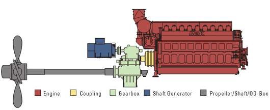
Position in the Plant
The gearbox sits between prime mover and shaftline as a mechanical interpreter. It translates engine output — high-speed, cyclic, and combustion-driven — into low-speed, high-torque rotation suitable for propulsion.
In doing so, it also becomes the structural boundary between the dynamic behaviour of the engine and the comparatively elastic behaviour of the shaftline and propeller. Any instability at this boundary propagates in both directions.
Gearboxes rarely fail suddenly. They accumulate distress quietly through tooth contact degradation, bearing fatigue, and lubrication breakdown. By the time noise or temperature alarms activate, the damage has often already spread.
Contents
Gearbox Purpose and Design Intent
Reduction, Torque Multiplication, and Load Paths
Gear Types and Contact Behaviour
Clutches, Couplings, and Engagement Philosophy
PTO / PTI Interfaces and Bidirectional Load Risk
Lubrication, Cooling, and Oil Reality
Control Under Real Operating Conditions
Failure Development and Damage Progression
Human Oversight and Engineering Judgement
1. Gearbox Purpose and Design Intent
The primary design intent of a marine reduction gearbox is controlled torque multiplication with predictable stiffness.
Engines are designed to operate efficiently at rotational speeds incompatible with propeller hydrodynamics. Gearboxes bridge this mismatch while absorbing:
- cyclic torsional excitation
- load transients
- misalignment between engine and shaftline
The gearbox must do this continuously, under varying load, without introducing unacceptable vibration or thermal stress.
A gearbox that “still turns” is not necessarily functioning correctly.
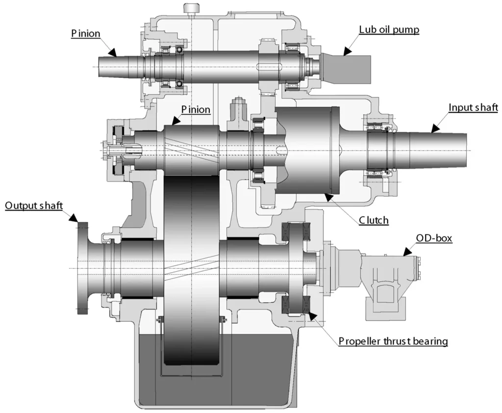
2. Reduction, Torque Multiplication, and Load Paths
Reduction increases torque in direct proportion to speed reduction. This amplified torque is transmitted through gear teeth, bearings, and casing structure.
The resulting load paths are complex:
- tooth contact forces
- bearing radial and axial loads
- casing distortion under torque
If alignment is compromised, load concentrates at tooth edges. This does not immediately raise temperature. It raises contact stress, accelerating pitting and micro-cracking long before alarms respond.
Gearboxes fail structurally long before they fail thermally.
3. Gear Types and Contact Behaviour
Marine gearboxes typically employ:
- helical gears for smooth load transfer
- double helical (herringbone) gears to cancel axial thrust
- planetary arrangements in high-power or compact designs
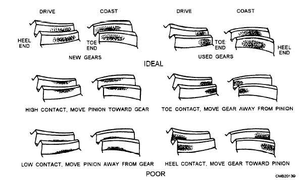
Gear tooth geometry is designed to spread load across the face width. Any deviation — misalignment, casing distortion, or bearing wear — disrupts this distribution.
Early damage manifests as:
- micro-pitting
- polishing of tooth flanks
- uneven wear patterns
These are not cosmetic defects. They are indicators of altered load paths that will worsen under continued operation.
4. Clutches, Couplings, and Engagement Philosophy
Clutches provide controlled engagement between rotating systems. They are not binary devices.
Marine clutches must absorb:
- speed mismatch
- inertia difference
- hydrodynamic resistance from the propeller
Improper engagement results in shock loading transmitted directly into gear teeth and shafting.
Common clutch failure contributors include:
- low oil pressure during engagement
- incorrect timing
- worn friction surfaces
- thermal distortion
A clutch that slips is not protecting the system. It is consuming itself while destabilising the load path.
5. PTO / PTI Interfaces and Bidirectional Load Risk
Power Take-Off and Power Take-In systems transform gearboxes into bidirectional machines.
While they provide operational flexibility, they introduce risk:
- reverse torque paths
- unexpected bearing loading
- control logic conflicts
Electrical PTI operation can impose torque patterns fundamentally different from combustion engines. Gearboxes not designed for this regime suffer accelerated fatigue.
Bidirectional capability must be treated as a structural condition, not merely a control feature.
6. Lubrication, Cooling, and Oil Reality
Gearbox lubrication serves three roles:
- separation of metal surfaces
- heat removal
- contamination transport
Oil degradation rarely causes immediate failure. It erodes margin.
Common degradation paths include:
- water ingress from coolers
- particle contamination from wear
- thermal breakdown at local hot spots
Oil analysis is not predictive unless trends are understood in context. A gearbox can operate “within limits” while tooth surfaces are already compromised.
7. Control Under Real Operating Conditions
Design conditions are rare.
Real operation includes:
- frequent clutching
- manoeuvring load reversals
- partial load operation
- heavy sea transients
Gearboxes tolerate these only when alignment, lubrication, and engagement discipline are maintained.
Automation controls speed and engagement.
Physics controls damage accumulation.
8. Failure Development and Damage Progression
Gearbox failures progress as:
- contact stress concentration
- micro-pitting and polishing
- bearing distress
- vibration propagation
- thermal instability
By the time noise changes character, corrective action options are limited.
9. Human Oversight and Engineering Judgement
No alarm announces incorrect tooth contact.
Engineers infer gearbox health through:
- vibration signature
- oil debris trends
- engagement behaviour
- temperature symmetry
A gearbox operating quietly but requiring increasing engagement time is not healthy. It is adapting.
Relationship to Adjacent Systems and Cascading Effects
Gearbox condition directly influences:
- shaft alignment
- bearing life
- propeller loading
- auxiliary power reliability
A distressed gearbox exports its problems upstream and downstream simultaneously.