Contents
- Purpose and Engineering Context
- Why Seawater Is Used (and Why It Is Inherently Dangerous)
- System Architectures
3.1 Direct (Open) Seawater Cooling
3.2 Central Cooling Systems - Seawater Intakes and Sea Chests
4.1 Hydrodynamics and Location
4.2 Fouling, Icing, and Collapse Risk - Strainers and Filtration
5.1 Simplex, Duplex, and Automatic Designs
5.2 Failure Progression and Human Factors - Seawater Pumps
6.1 Pump Types and Materials
6.2 Cavitation, NPSH, and Air Ingress - Seawater Coolers and Heat Rejection
7.1 Plate vs Shell-and-Tube Coolers
7.2 Fouling Margins and Thermal Drift - Water Chemistry and Corrosion Reality
8.1 Electrochemical Drivers
8.2 Galvanic Coupling and Hull Interaction - Control, Monitoring, and Early Warning
- Operational Limits and Engineering Judgement
- Relationship to Other Cooling & Heat Transfer Systems
1. Purpose and Engineering Context
Seawater cooling is the primary heat rejection mechanism aboard almost all seagoing vessels. Regardless of propulsion type, power density, or automation level, the ship ultimately rejects waste heat to the surrounding ocean. Every jacket water circuit, lubricating oil cooler, charge air cooler, refrigeration condenser, and hydraulic oil cooler depends—directly or indirectly—on seawater as the final heat sink.
From an engineering perspective, seawater cooling is not a “supporting system”. It is a boundary system, linking internal thermodynamic processes to an external environment that is chemically aggressive, biologically active, and mechanically unstable. The reliability of almost every other machinery system is therefore constrained by how seawater is introduced, controlled, and rejected.
Failures in seawater cooling rarely announce themselves dramatically. They develop silently through corrosion, fouling, erosion, or hydraulic instability, and they tend to propagate across systems. A compromised seawater circuit does not remain isolated; it degrades cooling margins everywhere.
2. Why Seawater Is Used
Seawater is used because it is abundant, continuously replenished, and has a high effective heat capacity. From a thermodynamic standpoint, it is an ideal infinite heat sink. From a materials and corrosion standpoint, it is one of the most hostile working fluids an engineer is forced to accept.
Seawater contains high concentrations of chlorides, dissolved oxygen, biological organisms, and suspended solids. Temperature, salinity, and oxygen content vary continuously with geography, depth, and season. Unlike closed freshwater systems, seawater chemistry cannot be stabilised or conditioned. The engineer does not control the fluid; the engineer merely survives it.
This creates a fundamental reality that shapes all seawater cooling design: no component is permanent. Pipes, coolers, pump casings, and valves are all consumable items with finite life. Design is therefore about managing degradation, not preventing it.
3. System Architectures
3.1 Direct (Open) Seawater Cooling
In direct cooling systems, seawater is drawn from the sea chest and circulated directly through engine jackets, exhaust manifolds, or auxiliary machinery before being discharged overboard. This arrangement was common on older vessels and smaller craft, where simplicity and low capital cost outweighed long-term degradation.
The engineering weakness of direct cooling is exposure. Every internal passage becomes a corrosion site. Scaling, biological growth, and erosion occur throughout the engine block. Temperature control is crude, and maintenance intervals are short. Once corrosion begins internally, repair options are limited and often uneconomic.
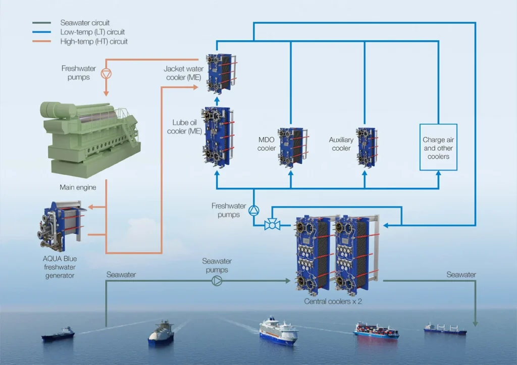
3.2 Central Cooling Systems
Modern ships overwhelmingly adopt central cooling architectures. In this arrangement, seawater is confined to a single boundary loop, typically circulating only through central coolers. Heat is transferred from freshwater systems—HT jacket water, LT circuits, lubricating oil—via heat exchangers.
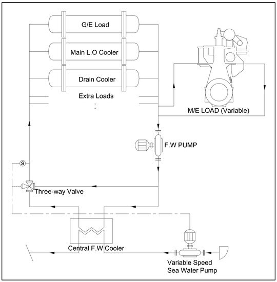
Central cooling does not eliminate seawater risk; it concentrates it. The advantage is control: seawater exposure is limited to known components that can be inspected, isolated, and replaced. The penalty is complexity and higher reliance on cooler integrity. When a central cooler fails, multiple systems are affected simultaneously.
4. Seawater Intakes and Sea Chests
4.1 Hydrodynamics and Location
Sea chests form the physical interface between the hull and the seawater cooling system. Their location is dictated by hydrodynamic considerations, draft variation, and vulnerability to blockage. Poorly positioned intakes experience air entrainment in heavy weather, sediment ingestion in shallow waters, or icing in cold climates.
From an engineering standpoint, sea chests must provide hydraulic stability. Turbulence, vortex formation, and uneven velocity profiles directly increase pump cavitation risk. The sea chest is not passive steelwork; it is a fluid-dynamic component whose performance affects the entire cooling chain.
4.2 Fouling, Icing, and Collapse Risk
Sea chests are prone to biofouling, debris ingress, and—in cold regions—ice formation. Blockage rarely occurs instantaneously. Flow restriction increases gradually, raising pump suction losses and reducing net positive suction head. The first symptom is often pump noise or fluctuating discharge pressure, not alarm activation.
Structural collapse of sea chest gratings has occurred on vessels operating in ice-laden waters, leading to sudden flooding of the intake compartment. These events underline a critical point: seawater cooling failures can escalate into hull integrity issues.
5. Strainers and Filtration
5.1 Simplex, Duplex, and Automatic Designs
Strainers protect downstream components from debris, marine growth, and sediment. Simplex strainers offer minimal redundancy and demand shutdown for cleaning. Duplex strainers allow changeover under load but rely heavily on correct valve sequencing and discipline. Automatic self-cleaning strainers reduce manual intervention but introduce reliance on control systems and purge functionality.
From an engineering reliability perspective, strainers represent a trade-off between mechanical simplicity and operational resilience. Automatic systems fail quietly when purge lines block or sensors drift, whereas manual systems fail noisily but visibly.
5.2 Failure Progression and Human Factors
Strainer failures are rarely due to structural breakdown. They result from delayed cleaning, incorrect valve alignment, or misinterpretation of differential pressure trends. In practice, many seawater pump failures trace back to partially blocked strainers that were “known” but tolerated.
This highlights a recurring theme in seawater systems: human tolerance of degraded performance is a major failure driver.
6. Seawater Pumps
6.1 Pump Types and Materials
Centrifugal pumps dominate seawater service due to their simplicity and steady flow characteristics. Materials range from cast iron with coatings to bronze, duplex stainless steels, and super-austenitic alloys. Material selection balances corrosion resistance, erosion tolerance, and cost.
No material is immune. Coatings fail first at high-velocity zones and near welds. Stainless steels suffer crevice corrosion under deposits. Bronze resists corrosion but erodes under high flow velocities.
6.2 Cavitation, NPSH, and Air Ingress
Cavitation is the most common destructive mechanism in seawater pumps. It results not from excessive discharge pressure but from insufficient suction head. Blocked strainers, air leaks, or elevated seawater temperatures reduce NPSH margin until vapour bubbles form and collapse within the impeller.
Cavitation damage is cumulative and irreversible. Once initiated, it accelerates erosion, increases vibration, and shortens bearing and seal life. Importantly, cavitation often persists unnoticed until performance loss becomes operationally significant.
7. Seawater Coolers and Heat Rejection
7.1 Plate vs Shell-and-Tube Coolers
Plate coolers offer high heat transfer efficiency and compact size but are sensitive to fouling and gasket degradation. Shell-and-tube coolers are more tolerant of debris and allow mechanical tube cleaning but occupy more space and require careful velocity control to avoid erosion.
From a system-design perspective, coolers are sacrificial components. They exist to fail before more valuable machinery does. Accepting this mindset fundamentally changes maintenance strategy and spare part planning.
7.2 Fouling Margins and Thermal Drift
Coolers are designed with fouling margins that assume gradual performance degradation. In practice, fouling is rarely uniform. Localised blockage leads to uneven heat transfer, thermal stresses, and eventual leakage between circuits. When seawater breaches into freshwater systems, corrosion accelerates dramatically.
Thermal drift—slow increase in operating temperatures—is often dismissed as seasonal variation. In reality, it is one of the earliest indicators of cooler degradation.
8. Water Chemistry and Corrosion Reality
Seawater corrosion is governed by chloride concentration, dissolved oxygen, temperature, and galvanic coupling. These variables interact continuously, making corrosion control probabilistic rather than absolute.
The hull itself participates in the electrochemical circuit. Bonding failures, stray currents, and poorly isolated fittings accelerate localised attack. Sacrificial anodes slow corrosion but do not stop it. Coatings delay exposure but degrade mechanically and chemically.
Most seawater leaks begin as pinhole corrosion, not gasket failure. By the time external leakage is visible, internal wall loss is often extensive.
9. Control, Monitoring, and Early Warning
Seawater systems are typically monitored indirectly through temperatures, pressures, and flow indicators. Direct condition monitoring is rare. This places heavy reliance on trend analysis and engineering intuition.
An experienced engineer recognises that stable readings at reduced margin are more dangerous than fluctuating readings with reserve. Seawater cooling failures rarely trip alarms until redundancy is exhausted.
10. Operational Limits and Engineering Judgement
Operating envelopes for seawater systems are defined conservatively, but commercial pressure often pushes vessels to operate in marginal conditions—high inlet temperatures, shallow waters, or fouled hull states. Each deviation consumes corrosion allowance and thermal margin.
Sound engineering judgement lies in recognising when continued operation converts degradation into damage. This decision is rarely procedural; it is experiential.
11. Relationship to Other Cooling & Heat Transfer Systems
Seawater cooling underpins HT and LT freshwater circuits, oil and fuel cooling, refrigeration condensers, and waste heat recovery. A single weakness propagates through all downstream systems.
Understanding seawater cooling is therefore not about mastering one system, but about appreciating its role as the foundation layer of the ship’s thermal architecture.